|
|
Post by highcooley on Apr 3, 2013 4:09:18 GMT -5
Glad it worked and your printer is finally tuned. I figured out that our wiki is a bit short on this behalf. Maybe you could contribute by explaining this process in your own words with a couple of pictures: sumpod.jumpwiki.com/wiki/Software |
|
|
|
Post by highcooley on Apr 2, 2013 3:02:25 GMT -5
Yes, exactly, you need to set "const int Z_MAX_LENGTH" correctly. To be able to do this, you have to make sure, that your bed is absolutely level to the nozzle (distance between nozzle and bed is always the same, independent from the x/y position of the nozzle).
If you homed Z in Replicator G (platform hitting the end-stop) and sent the command G1 Z0, the nozzle should stop somewhere above the print bed. Unless of course, you have already messed around with the max length and set it larger than the actual distance between the platform hitting the end-stop and the nozzle touching the bed. In this case, the nozzle will CRASH into the bed. So ALWAYS have one hand at the power switch when calibrating to immediately switch off to prevent crashes.
Let's assume, it didn't crash: Then, the bed should stop close to the nozzle. I don't use ReplicatorG, but I think the control needed is called jog control. Each time you click on the Z- arrow, the bed should move towards the nozzle the amount of mm set in jog mode. Use the jog mode setting and the Z- arrow to close in the gap between bed and nozzle until you are about 1 mm above the bed, always remembering how many mm you had to close in. For the last mm, set jog mode to 0.1mm. Then stick a piece of paper between bed and nozzle. To be as accurate as possible, heat bed an nozzle to working temperature now (both, the bed and the nozzle slightly expand when heated). When you reach temperature, start closing in this last mm, 0.1mm at the time. After each step, check if you feel a resistance when you move the paper between the bed and the nozzle. If this is the case, then you have found the right value for Z=0. Let us assume, that you moved the bed once for 10 mm, three times for 1 mm and seven times for 0.1 mm. So you end up with 13.7 mm. Add this value to the current z max length setting in your firmware and upload the firmware again. Zero your Z axis, heat bed and nozzle again and then move it 5 mm above bed level with the command G1 Z5. This is to make sure, you didn't do a mistake and the nozzle actually ends up 5 mm above the bed. Put the paper back in place, use G1 Z0 and check, if you still feel the same resistance. If this is the case, zero Z and go G1 Z0 directly a couple of times to make sure, this works flawlessly. If you feel more resistance, move the nozzle away in 0.1mm steps, if you feel less, move it closer. Reset your Z max length if necessary until zeroing works perfectly. When you are sure it works, do a test print (with proper zeroing with G28 in start g-code), abort after the first layer and measure the layer thickness. If it has the thickness that you set in your slicer software, congratulations, you just set your machine properly! Otherwise, finetune Z max length.
To "max_software_endstops = false": This means, that the software end-stop function is set to off. If you didn't add additional end-stops, your machine only knows the limit on one side of every axis. To prevent your machine from accidentally crashing on the other side, you can enable software end-stops. So, the machine does not move more than MAX_LENGTH (set independently for each axis) in any direction. Usually, you never give your machine a command to move further than that anyways. However, if you do a mistake, software end-stops prevent a crash. However, you should not enable software end-stops during calibration anyways and it also only helps, if you calibrated all three axes correctly.
I vaguely remember that there was a firmware issue once with these software end-stops. However, I don't know, if this was with sprinter or marlin and if it got resolved with the version of sprinter you are using. Best you calibrate and test max lengths. If your machine works properly, you can switch on software_end-stops. Just keep in mind that if your machine behaves strangely, this could be because of the software end-stops.
Ok, I hope, this helps and you are able to zero your machine properly. Otherwise, don't hesitate and ask again. There is also tons of information online about how to properly calibrate a 3D printer. I find the paper sheet method to be the fastest, easiest and accurate enough way to do it.
Cheers,
Andy
|
|
|
|
Post by highcooley on Mar 28, 2013 4:17:10 GMT -5
Hi sypher Can you explain a little more detailed, what you mean by "make use of my limit switch" and "move bed Z amount"? Do you mean, that your limit switch settings are not correct in the firmware and you have to manually adjust Z distance to bed before print? The process there would be to zero your machine, figure out the delta between nozzle and bed when both, bed and hot-end are heated up to working temperature and adding this value to max Z height in your firmware. Usually, you need to fine tune this value several times, until you get the first layer thickness correct. This can be done with the method of moving a sheet of paper between bed and nozzle and adjusting Z in pronterface until you feel a slight resistance when moving the paper. The heat up process for both, bed and hot end can be done automatically before print. This is done in your slicing software by editing the custom start g-code, using m-code commands and slicing software specific variables for both temperatures. The m-codes you need are M104 (set extruder temperature), M140 (set bed temperature), M109 (set extruder temperature and wait until target temperature is reached) and M190 (set bed temperature and wait). Depending on your taste, you can combine this codes, including a G28 (home all axis) code. I found an interesting combination here: www.soliforum.com/topic/231/improved-start-and-end-gcode/ which I haven't tried yet but find it interesting with it's anchor approach. If your power supply doesn't provide enough power to heat up both heaters from room temperature at the same time, I would first set and wait for the bed temperature and then go for the hot-end, since the bed needs a lot of power and takes much longer to heat up. Otherwise, set one temperature, then set and wait for the other and set and wait for the first temperature again to make sure, all target temperatures are reached. I hope, this was of help for you. Cheers Andy |
|
|
|
Post by highcooley on Mar 25, 2013 8:40:57 GMT -5
Hi
So far, I haven't heard about anyone buying a sumpod mega. I guess, you would be the first one (at least on this forum) :-)
As you say, there is not much that is known about this printer. However, from the pictures I would guess, that it is more or less an upscaled version of the sumpod aluminium. So, you would at least end up with the same hot-ends, which unfortunately don't work very well. Then there are the extruders, which are a bit different to the ones we have on the mdf sumpods. Nobody reported any problems with the aluminium extruders so far, but the design is similar and I would assume that you get about the same problems there. Last but not least, I doubt, that the moving z-platform is sturdy enough, as long as it is an upscaled version of the aluminium sumpod. However, as I don't know anything more than you, I can't say for sure. These are all assumptions only.
You say, the specs fit your needs. Out of curiosity, what huge objects do you plan to print with this machine? I don't know how much experience you have in hobby 3D printing. But the chance that such big prints fail is quite high. I'm printing with a Rostock max which I have tweaked for hours and spent quite some money for self made upgrades. And, although I could print 350 mm high objects, so far my biggest print was only 150 mm high. It took about 12 h to print. Unfortunately, there where about 10 layers mid print, which didn't bond correctly. 12 h printing time for nothing (and that's not the first object in this height category). By the way, even if you manage to print super fast, such huge prints will still take days to print.
It is not impossible to print in this scale, as a couple of prototypes (like the sumpod mega) by 3D printer manufacturers have proven. But unless you are a pro in hobby 3D printing, I would recommend to go for a smaller, proven to work machine until you feel saddle-fast to go bigger. 400 mm more way to zero your x,y&z axis will add up in trial and error time, as you will zero your machine thousands of time during the calibration process...oh yes, it is still annoying every time you have to wait for your machine to zero.
I don't want to say you shouldn't go for this printer. But since it is more in a prototype state (no proven to work machines out there) and many people have issues with their sumpod delivery anyway, I would think twice before buying a sumpod mega. Unless of course, you live close to Richard, have a broad know-how in hobby 3D printing, desperately need such a big printer and really like to develop a working sumpod mega together with Richard. Then I would recommend getting in touch with him and agreeing on a collaborative development.
I hope, I was able to help although I neither have any sumpod mega nor sumpod aluminium experience.
Cheers
|
|
|
|
Post by highcooley on Mar 14, 2013 5:07:35 GMT -5
Sad to hear, that you had to go full berzerk to get something, that is not even half baked. I hope, the few people on this forum, who actually risked it as well and got their sumpod aluminium, can help you out with the assembly. At least, if this is what you are looking for. Basically, hobby 3D printing is currently in a state where there is no out of the box solution. Even if you get a fully built printer, you are still going to spend ages to figure stuff out and to tweak your machine. After all what is said in the misleading glossy adverts and several media reports, these are still thinker machines. If you built your machine by yourself, it will at least help in the tweaking process. Generally, it seems to be some kind of disease, that many 3d printer kits come badly documented. Most of the time, it's the community providing excellent documentation after a short time (e.g. check out the sumpod wiki for the original sumpod: sumpod.jumpwiki.com/wiki/Main_Page). Unfortunately, there seems to be no big community around the aluminium sumpod. You could also check out forums about 3D printing to get the basic knowledge about 3D printer building. Many machines are quite similar and the same questions arise during the build process. However, after all a "fully assembled" machine should anyway come in less than 10 pieces which are easy to fit together. In my opinion, there is no excuse for that if you advertise an assembled machine. Good luck with what ever solution you are heading for! |
|
|
|
Post by highcooley on Jan 21, 2013 5:03:45 GMT -5
Hi Everyone, I am looking to buy a 3D printer also, but getting confused as to which one. Each time i think i have found one i see a lot of problems with delivery etc or low reliability (unless you go for the "budget" 2000 euro models). So far have looked into Printrbot + , RepRapPro, Sumpod, Soliddoodle. (all budget items). The sumpod Aluminium to me mechanically one of the best with the belt less X-Y drive but i was wondering if anyone here has worked with this machine yet. Also if it has the same problems with hot end etc etc as described in the above very nice and detailed account.. Hi aerogeek I cannot speak for the Sumpod Aluminium, as I have never seen one live. For the other printers, it all depends on where you live and what shipping costs you have to pay. A Solidoodle seems to be a nice printer, but the shipment to Europe is pretty expensive. I think, a Mendel Max (e.g. creativemachines.co.uk/store/index.php?id_product=9&controller=product) could be a good printer to go for. At least, that's what other people are saying and concerning the way it is built, it looks well designed and sturdy. I however just bought a Rostock Max from seemecnc.com, which is a fine machine as well. So far, I haven't enough experience with my new printer to recommend it, but it looks good on the way. |
|
|
|
Post by highcooley on Jan 15, 2013 20:29:01 GMT -5
Ok, here we go with the promised pictures: 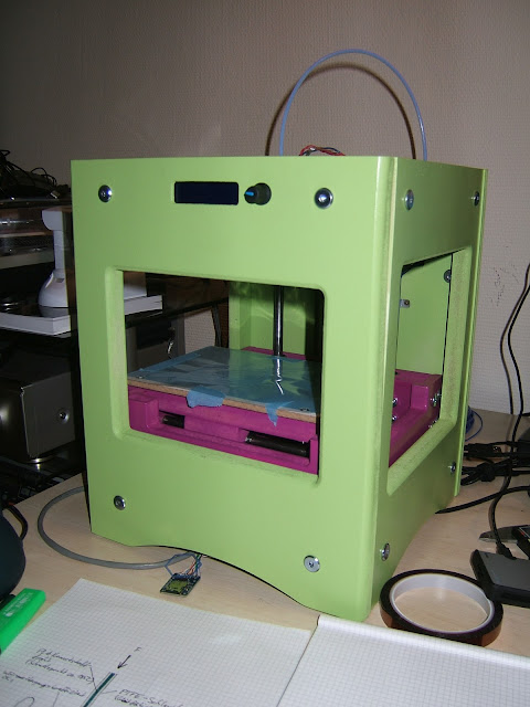  My own designed springs to hold the heated bed in place: 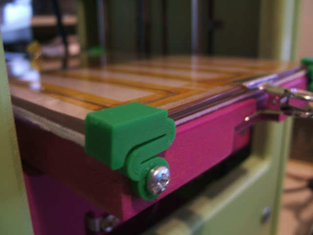 Additionally added plugs to comfortably unmount the hot-ends. Note the Z-axis handle to the left:  The white thing is a fan duct, which I designed to cool both, the hot-ends as well as the printing part at the same time. But I was not able to print it successfully, as a working fan would be needed to acomplish this difficult part (reprap's hen and egg problem). I canibalised the 40mm fan for my rostock, but a replacement fan is already bought and is ready to be installed: 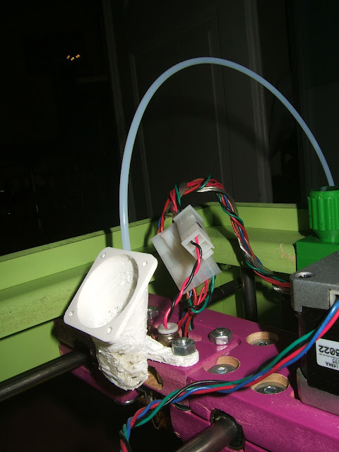 An improvised cooling channel into the hot-end mounting plate. Note, that the fan duct should go all the way down to the print bed:  The upgraded extruder I mentioned. The design was kindly shared by stohn. I only have one extruder printed today, as I wanted to print the other one as soon as I was able to print perfectly. But all the mechanical parts needed are ready to be installed: 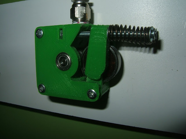 The CF card reader to print without a connection to a PC: 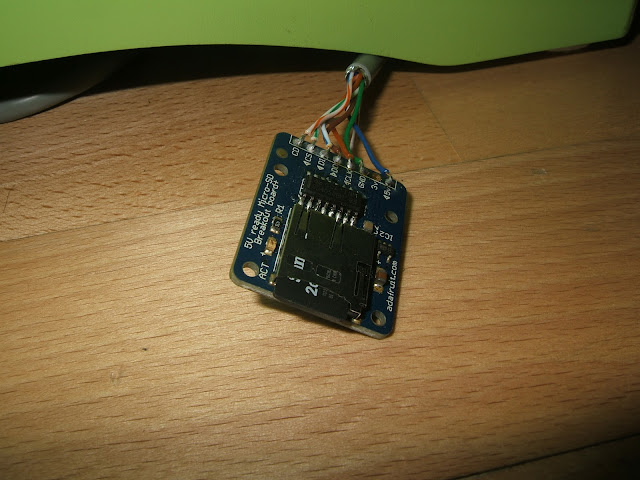 The bottom side of the printer with the electronics. I upgraded all five stepper drivers with heat sinks and added another driver circuit to control the hot-end fan. Currently, I operate the printer with two power supplies. The included supply for all the electronics, hot-ends and fans and an old PC power supply solely for the heated bed. Unfortunately, the PC power supply is allready at its limit when driving the heated bed and should be exchanged to a more recent one:  And here the three wear and tear things. First, the molten heated bed connectors:  The mount of the power connector broke from flipping the printer to the backside while the connector was plugged in for too many times during debugging:  One of the reasons for the jamming. The PTFE tube was stretched too much and burst, due to the filament expansion and a cavity inside the hot-end. Richard mentioned a fix for this (removing the two lowest threads from the PEEK insulator. I did this, but the problem is only partly solved...meaning, that it burst again: 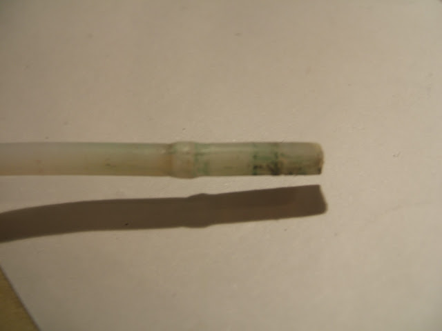 Here a couple of nice prints: 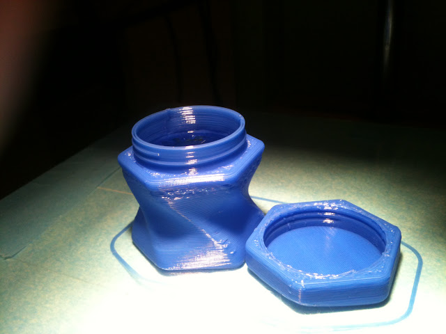  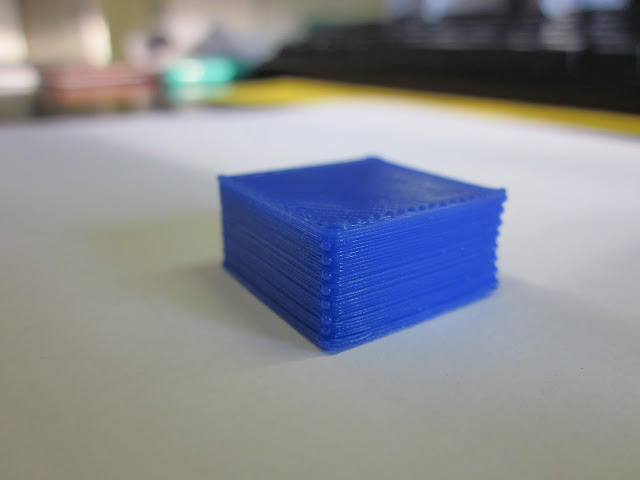 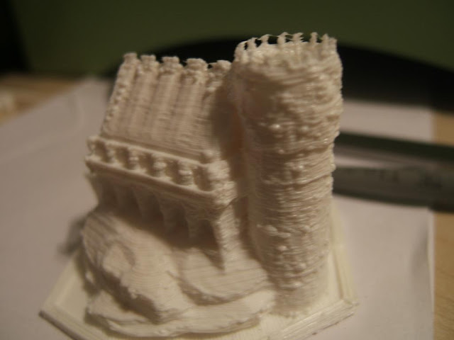 ...and the bad exemples: 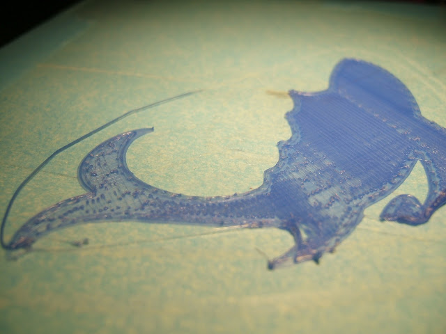 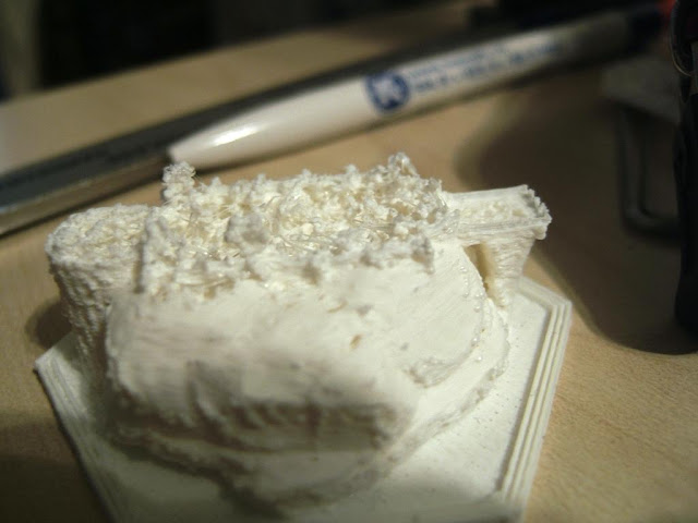   |
|
|
|
Post by highcooley on Jan 15, 2013 19:27:00 GMT -5
Both, extruder and hot-end are easily adjustable for both, 1.75mm and 3mm filament. The extruder has double hobbed bolts for both diameters and the mount is designed with two positions to lock in. The hot-end's inner tube (I think it's PET) is actually a combination of two tubes stuck inside each other. So they can be exchanged with one bigger tube for 3mm. The standard nozzle (which I am currently using) is 0.5mm and there are three other sizes available. I am currently printing 1.75mm filament @ 0.2mm layer height and 65/80 mm/s. The hot-end itself ist quite chunky with its hughe heater block (25mm in diameter). In contrast to most other designs I know, it has two 6.8Ohm resistors, one on each side of the inner tube, wired in parallel. So there is quite some juize flowing during heat-up phase. Interestingly, people report, that they need to set higher temperatures as compared to other hot-ends, using the same filament. I don't know, if it is the design, a bad temperature readout or just a bad thermistor table. Want to see my new upgrade? 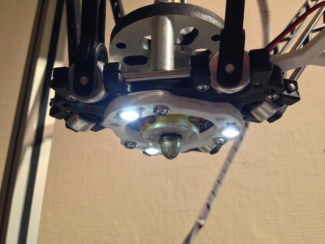 It's quite a light-show, but very useful! |
|
|
|
Post by highcooley on Jan 15, 2013 7:48:25 GMT -5
Yap, you're getting pictures soon.
Hmmm, despite being a former electronics technician, I would not describe myself as an expert in 3D printing. The Sumpod was my first printer and it all was and still is a big learning process. In retrospect, I would spend a bit more money for a proven to work printer, to spare myself all the trouble. It should still be a kit to build myself, as I enjoy building stuff a lot. But all needed parts should be included and more importantly, they should work if correctly configured. On the other hand, I learned a lot from all the issues and it helped me during the build of the delta printer.
Of course, you would have to build stuff like the mounting plate by yourself. And I know, it is a pain to do it without a fully equipped workshop. But so far, my Proxon and I where able to accomplish a lot of such stuff.
I think, as an electrician with knowledge in Arduino programming, you got all you need, to bring the printer to work. It is more a question of patience and endurance to get there with a Sumpod. However, although I cannot guarantee success with the measures I suggest, it should not need that much anymore, to make my Sumpod work.
In the end, that's the decision you have to take.
|
|
|
|
Post by highcooley on Jan 15, 2013 6:04:28 GMT -5
Thank you for your reply
Let me try to explain, what I mean with "not reliable enough":
After I configured my sumpod for hours, I can get very satisfying results with nice prints. This might work for a couple of prints (of different print times) without any issue. But suddenly, after a couple of perfect layers, the extrusion falters or the hot-end jams completely. There are a couple of explanations for this.
There is the whole hot-end issue. As also mentioned many times in the forum, the sumpod hot-ends don't always work as they should. The issue with PLA is, that it conducts heat very well, has a low glass transition temperature and swells, when it gets hot. In other words; the stiff filament turns gooey pretty fast, expands in the hot-end into all directions and the goo starts to grow along the filament. So, the bigger the gooey part, the lesser the force applied to the filament is getting passed straight down to the nozzle. The goo starts pressing to the sides of the hot-end tube, until the whole PLA goo-plug stalls, which is also known as jamming. To prevent this, newer hot-ends, including the sumpod's, have heat barriers installed (usually made of PEEK) to keep the heat close to the tip. But this is not enough, as even these PEEK parts slowly heat up. That's why most reprapers use a fan to keep the heat barrier cool (not to be mistaken as the cooling fan for the print). Now, with how the sumpod and the hot-ends are constructed, it is hard to keep these PEEK parts cold, as they are sitting inside the mounting adapter.
Somehow, also the aluminium nozzle seems to be a part of the problem. I am no expert in thermodynamics, but brass nozzles are widely agreed on, as working better than aluminium.
Then, there was the unreliable direct extruder, which stalled many times and chewed on the filament. This was the last thing, I got my hands on and was able to solve.
Another thing is the bed leveling problem, which is partly home made. We have the MDF print plate, which unfortunately is hanging a little bit to the front, due to how it is constructed with the rails on the back side. Additionally, my self made heated bed consists of a sandwich of MDF print plate, heat insulation mat, resistance wire and glass plate. You can imagine, that it is not very easy to bring the glass sandwich level on the sloped MDF plate. I installed set screws in each corner. But once the bed is level, it does not need much, to get off level again.
As mentioned before, probably the best approach would be to go for other, proven to work, hot-ends, including new mounts and a properly positioned fan (which is not to be sneezed at). Airtripper is testing J-heads, which look promising.
Then, I would disassemble and redesign the print bed, get rid of the chunky MDF plate, maybe install one made of aluminium, install more comfortable set screws and stick the sandwich onto these.
Do you get a feeling for what I mean? Unfortunately, most of these problems are not solved with the newer sumpod basic design either.
I'm gonna take a couple of pictures of the printer with its details and put them online tonight. I'll also include pictures of the more and the less satisfying prints as well as the parts to optimise.
Cheers,
Andy
|
|
|
|
Post by highcooley on Jan 14, 2013 10:23:46 GMT -5
Hello people Due to popular demand, I decided to write a review about my recently built Rostock Max by the US based company seemecnc.com. After hours and hours of more or less successful tinkering with my sumpod original, I was in desperate need of some fresh air. Don't get me wrong here; I am absolutely convinced, that a sumpod can be evolved into a reliable machine. However, I was fed up with spending a lot of precious money and time for even more trial and error. So I decided, it was time to see how other machines are built and how they work. Why a Rostock Max? The fast and ergonomic moving delta robots always fascinated me. However, many people building Rostocks reported additional problems to cartesian systems. A delta carriage has a lot of joints and connections, which have to be very rigid in order to provide accurate movement. The long timing belts, required to move the delta arms, are additional (possibly backlashing) parts in a long chain to bring the motor movement to the build plate. Obviously, self printed Rostocks need a lot of tweaking and fiddling, until they are accurate enough to print nicely. That's when Seemecnc's Indiegogo campaign came into play. I didn't know the company before, but a short research showed, that they successfully sold working reprap style printers with an own, working extruder & hot-end combination. Moreover, they construct mainly with rigid laser cut wood, metal and molded plastic. This, as well as the reasonable price convinced me to give the Rostock max a try. Three weeks after I pledged for the project, a huge parcel arrived, containing everything needed to build the machine (except 8 interchanged screws).  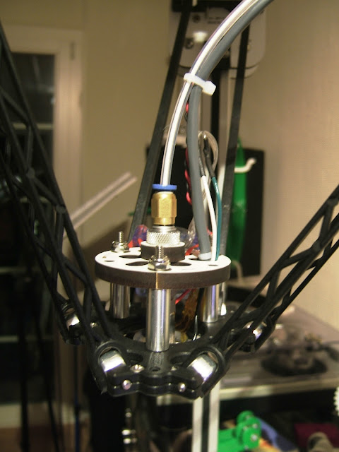 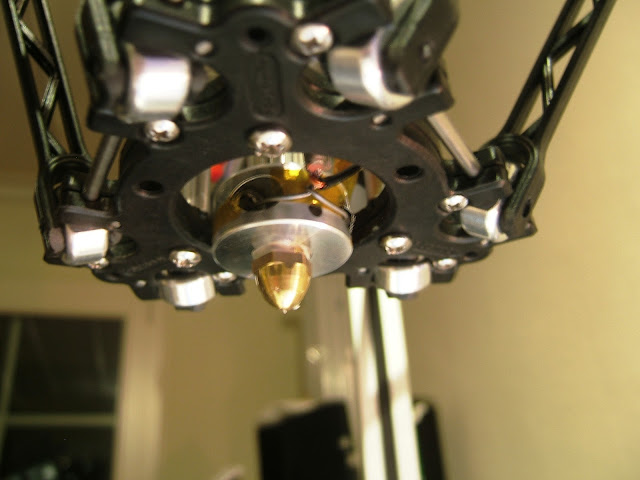 The build The buildTotal build time was about 15h for three engineers. Of course, the kit came with imperial parts, but most of them could be swapped with metric ones. Except for the missing screws, we had nothing to alter or to dig up additional parts. The kit is well manufactured and it is distinguishable, that skilled people with a lot of experience designed it. I was deeply impressed by all the neat construction details, which made life so much easier. For example the obvious things like doors to hide the cabling, prepared for adding cable straps, once everything is working fine. As well as slots to pas through the cabling to the front side:   The next gen RAMBO board is another neat feature :-) The configuration...went smoothly and very fast, thanks to an almost 100% pre-configured, functional marlin. Delta printer leveling and adjustment is different to other printers. Every time you adjust the endstop of one of the three axes, it affects both, Z-height and bed level in an unfamiliar way. It's a bit like balancing the tetrahedron on its tip. But in the end, you just have to get used to the system and adjust one axis after the other around the triangle for several times. The printingWell, I spare you all the ugly test prints which came out of the printer for a long time. The seemecnc guys mainly print with ABS, so there was no fan, neither a fan mount included in the kit. Also, PLA sticks to the included PC print surface like hell (it does not bond, but hardly comes off at all). To keep a long story short, the nozzle was oozing and the makeshift mounted fan, to cool the thermal barrier, slightly blew over the heating block. This caused temperature misreads, leading to too much heat and the partly melting of the PEEK part. The stop-the-ooze part was solved by fiddling with the nozzle tightening. The solution for the fan partly cooling the wrong parts of the hot-end was the design of a fan mount:  And that's how recent prints look like (the dent in the gear was caused by a temporary jam/stall, which never happened ever again since): 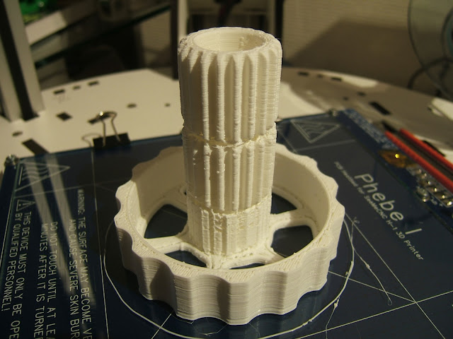    ...which leads to three remaining issues: One: The ugly surface which I don't know why it looks like this yet. Probably has something to do with print temperature. Two: The offset of perimeters and filling, caused exactly by the backlash, mentioned above. On recommendation of another Rostock user, I already tensioned the timing belts quite a lot. Maybe, I have to go even further or it has something to do with the joints of the carriage construction being too tight and causing the arms to bend slightly before moving. Three: Having a steady print bed is an absolute plus and makes life a lot easier...no change in angle or position, due to movement, nothing. However, what I underestimated is the movement due to thermal expansion. A flat glass surface is not exactly flat when heated and a screwed down heat bed bends when heated, as well. Anyways, that's where I currently stand with my Rostock Max. Not a perfect working printer yet, but already miles ahead of where I ever came with my sumpod. I learned a lot about correct hot-end cooling and I think, I could manage to get this print quality on the sumpod now. However, right at the moment the motivation to work on that is not very high, sitting next to a working printer :-) To sum up: + Nicely engineered, complete kit + Very rigid construction + Working hot-end and extruder + Exemplary customer support and well managed forum - Feared backlash occurred and is not yet resolved - Build vlog is pretty tedious and the user written manual not yet perfect and complete - Not fully prepared for PLA printing (missing fan, mount and optimal print surface), but the hot-end works well More information about my build can be found on my buildlog on seemecnc's forum: forum.seemecnc.com/viewtopic.php?f=42&t=1036Thank you for your comments and questions! Cheers, Andy |
|
|
|
Post by highcooley on Jan 14, 2013 7:20:59 GMT -5
Hey Patrik,
As Mark mentioned, the main problem for the delays are probably the electronic components. A hardware only version should hopefully ship faster. Just agree on a shipping date with Richard.
One thing to consider in comparison to the solidoodle is, that the sumpod basic is a kit and not a plug-and-play machine which comes configured and tested. In my experience, you need some basic technical skills to do minor adjustments by yourselves (drilling, filing, sanding, soldering).
I personally would not wait for a sumpod delta at the moment. The odds to get a machine with teething problems are quite high, as we haven't seen a working sumpod delta so far.
What I could offer you is my sumpod original, which is similar to the basic version. On the hardware side, the following is different: The MDF cutouts to access the build area are a bit smaller, it is belt and not rack gear driven and it is a dual head version with the latest sumpod hot-ends. The electronics are a RAMPS 1.3 plus arduino board, an LC display and an additional CF card reader.
I made the following changes / upgrades: Extruders similar to airtripper's design with MK7 drive gears, a heated bed with borosilicate glass plate as well as airtrippers z axis handle.
It is obviously a used machine with visible marks. On the other hand, I spent days for configuration and optimisation, which could spare you a lot of trouble. However, the printer still does not print reliable enough to me. These are the changes, I would have made next: Upgrade to other hot-ends, as richard's tend to jam too often, design a proper fan mount to cool the hot-ends as well as the print, optimise the bed mount and add a better leveling mechanism.
The reason, why I haven't already done these changes are, that I purchased a Rostock Max by seemecnc.com in the meantime. I needed a change, as I already spent too much time (and a lot of money) on my sumpod. From what I learned from the Rostock build, I now know what I would have to do to make the sumpod work. However, having a working printer now, the motivation to make my sumpod work is not very high at the moment.
PM me, if you are interested. I could also post pictures, if you like.
Cheers,
Andy
|
|
|
|
Post by highcooley on Jan 13, 2013 12:46:56 GMT -5
In this case, I would also not wait any longer and try to get the money back by bank/paypal.
Cheers and good luck!
Andy
|
|
|
|
Post by highcooley on Jan 9, 2013 5:27:44 GMT -5
Yes, definitely check back with Richard first, before you haul out the big guns. I'd suggest to ask (one more time / the last time), when he can deliver and issue an ultimatum. Agree on how you will precede, if he can't deliver until the set date. Unless of course, you don't want your machine anymore, at all. Then I would just agree on how to precede to transfer the money back.
I fully understand your intolerable situation. But too many unnecessary nasty wars are being fought out on court nowadays, because of lack of communication. Besides, I remember Richard promising that he wants to work on his inadequate communication. Confront him with his promise.
|
|
|
|
Post by highcooley on Jan 8, 2013 6:40:58 GMT -5
:-) A nice approach indeed I cannot comment on metal beds, but I read this article back when it was released, and I was similarly baffled at first. However, on the second thought, it neither replaces a flat bed, nor does it replace a proper level one. But of course, this method can be of help for measuring everything. You could even think of rudimentary "scanning" objects to print later, in a method similar to a scanning electron micrograph. Would it really help for uneven beds? I don't think so. Moving the Z axis along an uneven bed surface during print would maintain the correct distance to the nozzle. However, the print layers would also follow the same unevenness. In other words, you would have the same bumps throughout the whole structure of your print as you have in your bed. So, you still want a surface as flat as possible. Would it help to compensate for a not correctly leveled bed? Only partly. If the Z axis would only follow the inclination of the bed, the whole print would be shifted in parallel. You could do the math and rotate the whole object to lay flat on the bed, ahead of slicing. The print would turn out in correct geometry, but this time, each layer of the print would be slightly shifted to the one before, leading straight vertical walls to turn out staggered. Of course, I could be wrong, and the correction of a slightly uneven bed would improve print quality, leaving the staggering unnoticeable. For me, the effort for such small corrections seem to be quite big at the moment. However, another interesting application of a Z min probe is to home the nozzle to the bed instead of Z max, simplifying correct Z height adjustment in the firmware. This has been done by several people in different ways (e.g. www.thingiverse.com/thing:7550). This method is pretty thrilling to me. But so far, I don't fully trust it, as the mechanics to move the probe out of the way during print, is not to be sneezed at (of course, you could use another set of sensors, to make sure, the probe is in full up or down position). I wouldn't want to see my nozzle crash into the glass bed at full speed, due to the probe not being in the right spot at the right time. I hope, I didn't disenchant you with my view on this method. It surely would be very interesting to see, what other uses people could find for it. By the way, in some G-code descriptions for marlin, you can find a set of codes for auto leveling. However, I didn't check if they are already/ still implemented, but it might be worth a try. Happy printing Andy |
|
